
Printing will then be intermittent or stop completely until the coil temperature falls below the limit value.Ģ.2.2 Spacing Operation (See Figure 2-4.) When the temperature of the coil exceeds a pre-determined limit (about 119 ☌) the control circuit detects a thermistor signal. (c) After the character has been printed, the armature is magnetically attracted again and the print wires are again concealed under the wire guide.Ī thermistor in the printhead prevents burning caused by over-heating of the coilĭuring extended continuous bi-directional printing. The print wire fixed to the armature protrudes from the tip of the wire guide, strikes the paper through the ribbon and prints a dot on the paper. The armature is driven in the direction of the platen by the force of the armature spring. When the coil is activated, the magnetic flux (caused by the permanent magnet between the armature and the core) is canceled to eliminate the attraction force. (b) When a signal for a character to be printed is detected, a current flows through the coil. The print wires fixed to each armature are thus concealed under the wire guide. (a) When the printhead is idle, the armature is attracted by a permanent magnet and the spring fixing the armature is compressed. (2) Operation of printhead (See Figure 2-3.) to control and maintain the impact necessary for each printing pin at the fixed value. The head drive time is lengthened to compensate for the amount of voltage drop by monitoring the POWLEV signal once every 500 μ sec. + 40V is converted into the POWLEV signal (0V to +5V) by R28 and R29 and input into the A/D port of the MPU to control the drive time and the print speed (pass number) of the head. (2) Alarm processing when DC power is low. This cause the secondary coil (40V) of the transformer to be short-circuited, causing an overcurrent to flow through the primary coil and making the AC fuse (transformer assy) open. If the drive time of any drive circuit exceeds the specified time, the drive fault alarm circuit sends an ALARM-N signal to turn on the SCR (SO). This circuit monitors the drive time using the HDALM signal interlocked with the overdrive signal of each drive circuit. The program here sets the mode of the LSI including the MPU, checks the memories (ROMs and RAMs), then carries out carriage homing, and determines the LF motor phase.įinally, the program establishes the interface signals (P-I/F: ACK-P signal sending, and S-I/F: BUSY-N signal off) and lights the SELECT lamp to inform the ready state for receiving to the host side and ends the initialize operation.

Reset operation by I-PRIME starts program to initialize, but does not reset the MPU. When resetting ends, the program starts and the LSIs are reset by MPU via LSIRST-N. This printer is initialized when the power is turned on or when the I-PRIME-N signal is input from the host side via the parallel interface.įor the initialize operation, the RST-N signal is first output from the reset circuit to reset the MPUs and LSIs.
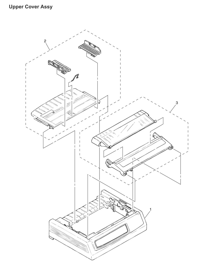
OKIDATA MICROLINE 320 TURBO DIAGRAM DRIVER
The function of this microprocessor is to provide a central mechanism for the entire printer by executing the control program through the LSI and driver circuits.


 0 kommentar(er)
